
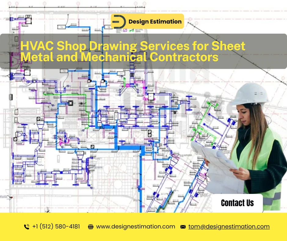
Design drawings show where systems should go; shop drawings show exactly how they will be built. For sheet metal shops, they also feed fabrication and cut lists. This guide explains what HVAC shop drawings include.
How this guide was prepared: written and reviewed by the Design Estimation drafting and estimating team, led by founder Austin Smith (7+ years in construction estimating and drafting). Every sheet we issue is drafted to the engineer’s design and checked by a person before delivery.
What HVAC Shop Drawings Include
| Drawing | Content |
|---|---|
| Duct layouts | Sizes, elevations, fittings, dampers and access doors |
| Fitting details | Elbows, transitions and takeoffs for fabrication |
| Piping layouts | Hydronic and refrigerant piping, valves and specialties |
| Equipment plans | Units, curbs, clearances and connections |
| Sections | Coordination at tight areas and crossings |
| Hanger and support details | Supports, seismic bracing where required |
| Submittal set | Sheets and data for engineer review |
Fill in your details and we’ll get back to you with a quote.
- Quote reply within 1 hour
- Estimates in 24–48 hours
- Prepared by human estimators
Design Drawings vs. Shop Drawings
Engineer’s drawings are often single-line and diagrammatic. Shop drawings show real duct sizes, insulation, fittings and elevations, and they resolve conflicts with beams, sprinklers, cable tray and lights. See our guide to what shop drawings are.
LOD 350 vs. LOD 400 for HVAC
| LOD 350 | LOD 400 | |
|---|---|---|
| Purpose | Coordination between trades | Fabrication and installation |
| Duct and pipe | Correct size, routing and elevation | Exact fittings, joints, connectors and lengths for the shop |
| Hangers and supports | Shown where they affect clearance | Every hanger and support located |
| Used for | Clash detection and coordination sign-off | Fabrication export, spool sheets and field layout |
Most HVAC shop drawing packages are modeled to LOD 350 for coordination, then taken to LOD 400 for the areas the shop will fabricate. Our BIM level of development guide explains each level.
From Coordinated Model to Fabrication
- Model the ductwork and piping in Revit with the specified gauge, pressure class, insulation and fitting types.
- Coordinate with structure, sprinklers, plumbing, electrical and ceilings, and run clash detection in Navisworks.
- Issue the submittal set of plans, sections and details for engineer review.
- Revise to review comments and resubmit until approved.
- Export for fabrication: fitting and straight-run data for the shop’s fabrication software, such as CAMduct, and spool sheets for piping.
- Issue field drawings with hanger locations and elevations for installation crews.
Standards and Coordination
- SMACNA: duct construction, reinforcement and sealing by pressure class.
- Specifications: gauge, materials, insulation and testing.
- Coordination: MEP and structural overlays, ideally in a BIM model, so clashes are resolved before fabrication. See our MEP shop drawing guide.
Regional Requirements
Seismic regions need bracing details; hurricane regions need equipment anchorage and wind-rated curbs; local codes may add fire and smoke damper requirements. Shop drawings should reflect the requirements in the contract documents and local code.
Typical Package: Three-Storey Medical Office
| Sheet set | Contents |
|---|---|
| Floor duct plans (3 levels) | Duct sizes, bottom-of-duct elevations, dampers and access doors |
| Roof plan | RTU curbs, duct penetrations and equipment clearances |
| Mechanical room plan | Piping, valves, pumps and equipment connections |
| Sections | Tight corridors where duct, sprinkler mains and cable tray cross |
| Details | Hangers, seismic bracing, fire damper installation and duct connections |
| Fabrication data | Fitting and straight-run export for the sheet metal shop |
Medical buildings carry more fire and smoke dampers, higher air change rates and tighter ceiling spaces than standard offices, so coordination sections and damper details make up a larger share of the package.
What to Send
- Mechanical design drawings and specifications.
- Architectural and structural backgrounds or models.
- Equipment submittals.
- Your CAD or Revit standards and fabrication preferences.
How Design Estimation Helps
We prepare HVAC and MEP shop drawings in AutoCAD and Revit through our shop drawing services, and can also provide duct takeoffs for pricing. For full-building MEP coordination drawings, see our MEP drafting guide. Send your drawings.
Share This Entry
Frequently Asked Questions
Quick answers to the questions contractors ask us most.
What are HVAC shop drawings?
They are detailed fabrication and installation drawings for ductwork, piping and equipment, prepared from the engineer’s design.
Do HVAC shop drawings follow SMACNA?
Yes. Duct construction, reinforcement and sealing follow SMACNA standards and the specifications.
Are shop drawings coordinated with other trades?
Yes. They are overlaid with structural and other MEP systems so conflicts are resolved before fabrication.
Can you produce shop drawings in Revit?
Yes. We work in AutoCAD and Revit, depending on the project requirement.
How fast can HVAC shop drawings be prepared?
Timing depends on project size; we confirm the delivery date before starting, and engineer redlines are typically turned around within 24 hours.
Are shop drawings prepared by AI or human drafters?
Our shop drawings are prepared and checked by experienced human drafters.
What is the difference between LOD 350 and LOD 400 HVAC drawings?
LOD 350 is for coordination; LOD 400 is for fabrication. LOD 350 shows correct sizes, routing and elevations to resolve clashes. LOD 400 adds exact fittings, joints, hangers and lengths so the shop can fabricate from the model.
Related Articles
 Articles · 8 min readWhat Are Shop Drawings? Shop vs. Fabrication vs. Construction DrawingsRead Article →
 Articles · 11 min readPrecast Detailing Services: Shop Drawings, Connections and Erection PlansRead Article →
 Articles · 8 min readTypes of Construction Drawings and Documents (Plus BOQ vs. BOM)Read Article →
 Articles · 8 min readWhat Is MEP in Construction? Systems, Drawings, Coordination and EstimatingRead Article →
 Articles · 10 min readRebar in Footings, Slabs and Stirrups: Spacing, Layout and Bar Bending SchedulesRead Article →
 Articles · 3 min readRebar Shop Drawing Services and Bar Bending SchedulesRead Article →
Get Fabrication-Ready HVAC Shop Drawings
Send your mechanical drawings and standards. We'll confirm scope, price and delivery date before any work starts.