
BIM Modeling & VDC Coordination Services
We engineer submittal-ready Autodesk Revit 3D models and Navisworks coordination sets for general contractors, engineering firms, and MEP subcontractors. In fact, identifying trade overlaps in preconstruction resolves up to 80% of field RFIs, stops budget bleeding, and ensures your crews build without rework.
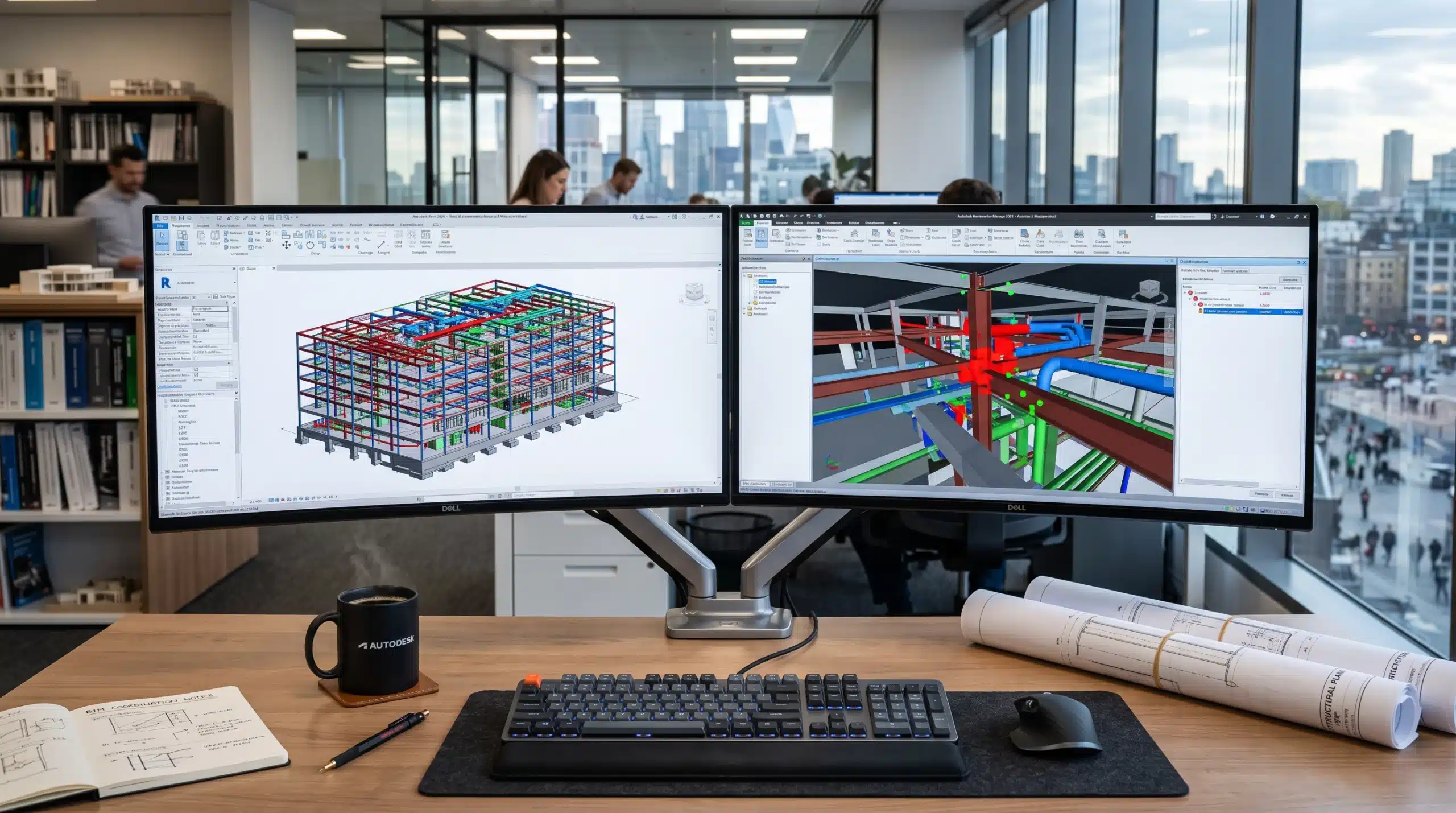
Specifically, our in-house BIM workflows integrate real-time 3D spatial coordination alongside precision 2D submittal detailing.
Up to 80%
Reduction in Field RFIs
100% Clash-Free
Pre-Fabrication Verification
15%–20%
Faster Trade Installation
Zero Rework
Protected Subcontractor Margins
Comprehensive VDC & BIM Modeling Solutions
Generic design blueprints frequently lack spatial coordination. For this reason, our virtual design and construction (VDC) workflows convert architectural intent into constructible, data-loaded models.
Mechanical, Electrical & Plumbing (MEP) BIM
Ceiling plenums in modern commercial buildings are congested battlegrounds. Specifically, duct mains, fire sprinkler lines, cable trays, and sanitary pipes compete for identical clearance. To prevent installation gridlock, our team creates parametric MEP components in Revit. Consequently, every routing detail accounts for pipe slope, insulation thickness, and hanger brackets so your subs install without field modifications.
Structural Steel & Rebar Concrete BIM
Our engineers build structural models up to LOD 350 and LOD 400 that accurately reflect load-bearing configurations. In addition, our draftsmen detail rebar cage clearances, anchor bolt locations, and steel connection gussets. As a result, fabricators verify embed placements well before transit mixers arrive at the jobsite.
Architectural BIM & Building Envelopes
Architectural design models require clean geometric data to serve downstream trade execution. For instance, our modelers build parametric Revit families with verified thermal zones and exterior glazing assemblies. Because our models maintain strict dimensional control, your submittal packages navigate architect reviews with minimal redlines.
4D Construction Phasing & Simulation
In contrast to standard plans, static Gantt charts fail to communicate spatial logistics across crowded jobsites. By linking schedule parameters directly into 3D models, we produce visual construction simulations. Furthermore, project managers can preview crane radius clearances, laydown areas, and concrete pour sequences to prevent trade congestion before crews mobilize.
5D Cost Takeoffs & Preconstruction Estimating
Accurate bidding demands automated quantity extractions tied directly to physical building geometry. Therefore, our 5D BIM workflow links Revit schedules with our preconstruction estimating databases. As a consequence, takeoffs for concrete volume, steel tonnage, and duct surface areas automatically reflect every design revision in real time.
Laser Scan to BIM (Point Cloud Conversion)
Renovation and retrofit projects rarely match historical paper blueprints. For this reason, our team converts raw 3D LiDAR point clouds into millimeter-accurate Revit geometries. Ultimately, this reverse-engineering step prevents your field crew from hitting hidden structural bulkheads or unrecorded utility lines.
Navisworks Clash Resolution Matrix
We do not just run automated software audits. Instead, we resolve spatial clashes systematically across all building systems.
1. Hard Clashes
First, hard clashes represent direct physical intersections where two components occupy identical spatial coordinates. For example, an 18-inch supply duct may penetrate an engineered steel beam or a foundation pile cap. Consequently, we adjust elevations and offsets to eliminate these overlaps before fabrication.
2. Soft / Clearance Clashes
Second, soft clashes involve violations of required operational or safety buffers. Specifically, high-voltage conduit runs must respect minimum clearance distances from steam lines according to building codes. Therefore, we configure dedicated service corridors around all valve manifolds and equipment access panels.
3. Workflow / 4D Clashes
Finally, workflow clashes arise from construction sequencing conflicts where one subcontractor’s work physically blocks another trade. As a result, resolving these staging issues early prevents costly jobsite downtime and union jurisdictional disputes.
Level of Development (LOD) Delivery Matrix
To begin with, choose the precise depth of modeling detail required for your current preconstruction or fabrication phase.
| Milestone Phase | Geometric Detail | Data & Specification Depth | Primary Contractor Application |
|---|---|---|---|
| Concept (LOD 100) | Conceptual massing, overall volume, and spatial orientation. | Rough square footages, project area boundaries, and height limits. | Primarily used for early feasibility studies, urban zoning reviews, and conceptual cost modeling. |
| Schematic (LOD 200) | Generic assemblies with approximate size, shape, and placeholder locations. | System types identified with generalized material layers. | In addition, suitable for early design approvals, space planning, and baseline MEP sizing. |
| Detailed (LOD 300) | Specific assemblies with precise dimensions, locations, and structural interfaces. | Detailed materials, equipment tags, and verified design parameters. | Consequently ideal for permit document submittals, architectural validation, and bidding takeoffs. |
| Coordinated (LOD 350) | Model components detailed with physical connection interfaces and clearances. | Anchor bolts, connection brackets, weld callouts, and support framing. | Specifically applied to multi-trade clash resolution in Navisworks and field installation planning. |
| Fabrication (LOD 400) | Fabrication-ready geometry detailed with exact manufacturer part numbers. | Full assembly guides, shop cutting parameters, and pipe spool dimensions. | Therefore utilized for off-site MEP prefabrication, CNC plasma cutting, and direct shop manufacturing. |
| As-Built (LOD 500) | Field-verified, as-built spatial conditions confirmed after site delivery. | COBie parameters, manufacturer serial numbers, and maintenance schedules. | Finally deployed for facility management, asset tracking, and ongoing building lifecycle maintenance. |
Connected Preconstruction & Regional Code Compliance
BIM models reach maximum value when directly integrated with fabrication documents and bidding data. For example, our modelers translate coordinated models into shop-level submittal packages through our specialized CAD Shop Drawing Services to keep steel fabricators and mechanical shops operating at peak efficiency.
In addition, sitework quantities must correlate with building pads. Consequently, pairing your BIM coordinates with our verified Cut and Fill Calculations secures exact grading, excavation, and fill volumes before site preparation begins.
Furthermore, our VDC packages are calibrated to strict municipal codes. Whether you are building under strict seismic standards in California, bidding commercial facilities in Texas, or managing wind-load mandates in Florida, our coordinated models help your projects clear municipal reviews promptly.
Software Stack & Export Formats
Additionally, we collaborate seamlessly across your existing project common data environment (CDE).
Core BIM Modeling
Autodesk Revit (RVT), AutoCAD Architecture, Navisworks Manage (NWD / NWC), and Autodesk Construction Cloud / BIM 360.
Fabrication & Detailing
In addition, we deploy SysQue, Fabrication CADmep, Tekla Structures, and SDS/2 for steel connection integration.
Open BIM & Interoperability
Furthermore, we support Industry Foundation Classes (IFC 2×3, IFC4), BCF (BIM Collaboration Format), and 3D DWG.
Submittal Deliverables
As a result, you receive high-resolution vector PDF packages, native Revit files (.RFA), Navisworks clash reports, and Excel summaries.
Our 4-Step VDC Coordination Workflow
Here is how we guide your project from initial design handover to a 100% clash-free sign-off.
Model Ingestion & Audit
First, we assemble your architectural prints, structural engineering files, and equipment cut sheets into a unified Revit project workspace with confirmed coordinates.
Trade Modeling & Routing
Next, our team models all MEP trades, structural assemblies, and architectural elements up to the agreed LOD, ensuring proper insulation clearances.
Navisworks Clash Audit
Subsequently, we execute hard and soft clash audits to flag trade overlaps and provide practical re-routing solutions for trade approval.
Sign-Off & Extraction
Finally, we publish coordinated federated models, verified shop submittal sheets, and fabrication spool drawings ready for site deployment.
Frequently Asked Questions
What is the difference between standard CAD drafting and BIM services?
CAD produces flat, two-dimensional geometric lines that show basic dimensions without embedded intelligence. On the other hand, BIM develops parametric 3D models containing real-world material properties, model numbers, flow rates, and cost data. Consequently, when an element updates in BIM, every associated elevation, section, and schedule automatically updates across the entire project.
Can you lead weekly multi-trade BIM coordination meetings with our subcontractors?
Our VDC managers frequently act as the lead BIM coordinators for commercial general contractors. Specifically, we chair weekly online clash meetings, present filtered Navisworks viewpoints, and assign actionable resolution tasks to trade subs. As a result, project teams eliminate delays and track RFI closeouts until the federated model is fully signed off.
What files do you need from us to begin modeling?
We accept all standard architectural, structural, and MEP engineering drawings in PDF or DWG format. In addition, we incorporate equipment cut sheets, structural specifications, and existing architectural Revit files as our project coordination baseline.
How do you prevent hundreds of false-positive clashes in Navisworks?
Automated software audits frequently report thousands of irrelevant clash notifications. To eliminate this noise, we build customized search sets and tolerance rules inside Navisworks Manage. Therefore, your trade teams focus strictly on critical structural penetrations and trade crossovers.
Can you extract preconstruction quantity takeoffs directly from the Revit model?
In fact, one of the primary benefits of our 5D BIM workflow is automated quantity extraction. Because every wall, duct run, and footing is modeled to exact dimensions, our estimators generate verified takeoff sheets for material procurement and bid tracking.
What is your typical turnaround time for an initial clash report?
For mid-sized commercial projects, we usually deliver initial federated models and the preliminary clash detection matrix within 4 to 6 business days. Furthermore, expedited milestone delivery is available for urgent bid deadlines.
Ready to Eliminate Jobsite Clashes Before Breaking Ground?
Upload your architectural sheets, trade specifications, or 3D scan data today. As a result, you will receive a comprehensive VDC proposal and guaranteed turnaround schedule within 4 hours.